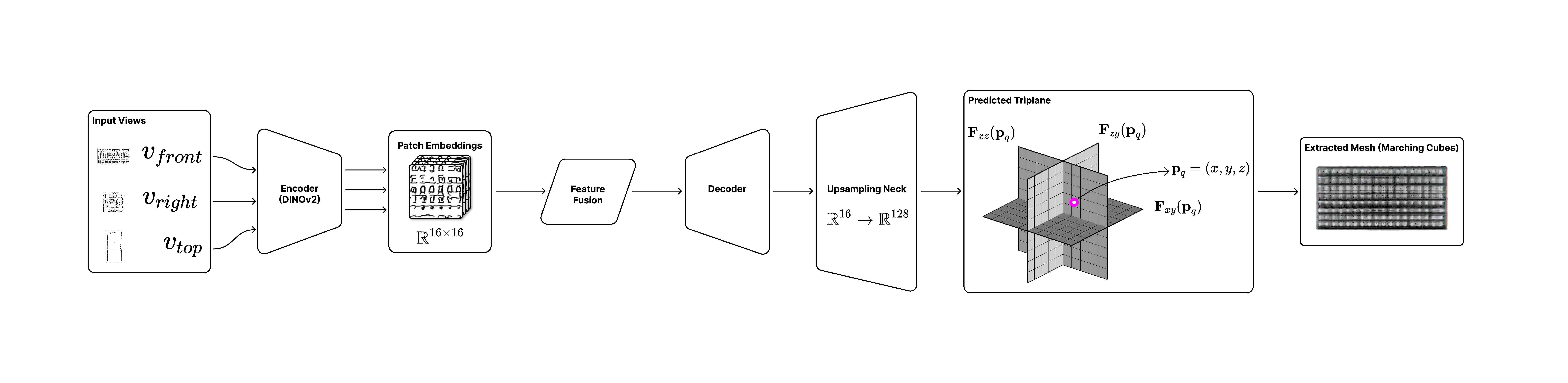
Given three orthographic “napkin sketches” (top, side, front view) of a building, can a deep model produce a detailed 3D model of that architecture? We built a Vision Transformer pipeline — a frozen DINOv2 encoder plus a custom transformer decoder — that maps the three sketches to a triplane 3D representation, from which a mesh is extracted with Marching Cubes. Trained on a dataset we generated ourselves because no existing architectural 3D dataset was good enough.
Designers think in sketches. Three orthographic napkin sketches — plan (top), elevation (front), and side — capture most of what a building wants to be. Existing 3D-synthesis models are built for object-centric domains (chairs, cars, ShapeNet categories) and struggle to hold the structural integrity and spatial coherence architecture needs. 3T3D asks whether a ViT-based, sketch-conditioned model can do better for buildings, and how you’d build one end to end when the training data doesn’t exist yet.
This was the 11-685 Introduction to Deep Learning final project (Spring 2025), a four-person team of CMU architecture/computational-design students. I am first author on the writeup. The same core trio reunited in Fall 2025 for the [[2025-Fall—l43d-cad-mllm|CAD-MLLM L43D project]] — 3T3D was the DL warm-up, L43D the multimodal sequel.
Problem & framing
- Goal. A design tool an architect could use to generate 3D iterations of simple sketches in near real time — three inputs (plan + two elevations) chosen deliberately so the designer keeps full control of the resulting form.
- Why it’s hard: 3D-aware generative models are optimized for object-centric tasks and don’t preserve the spatial/hierarchical relationships buildings require. We frame this as controlled 2D→3D generation conditioned on sketches.
- Relation to prior work: we build on the 3D-aware conditional-synthesis idea from pix2pix3D (Deng et al.), but condition on sketches rather than label/segmentation maps, and adopt the triplane 3D representation from Neural Field Diffusion (Shue et al.) — swapping their diffusion generator for a ViT encoder-decoder.
Architecture
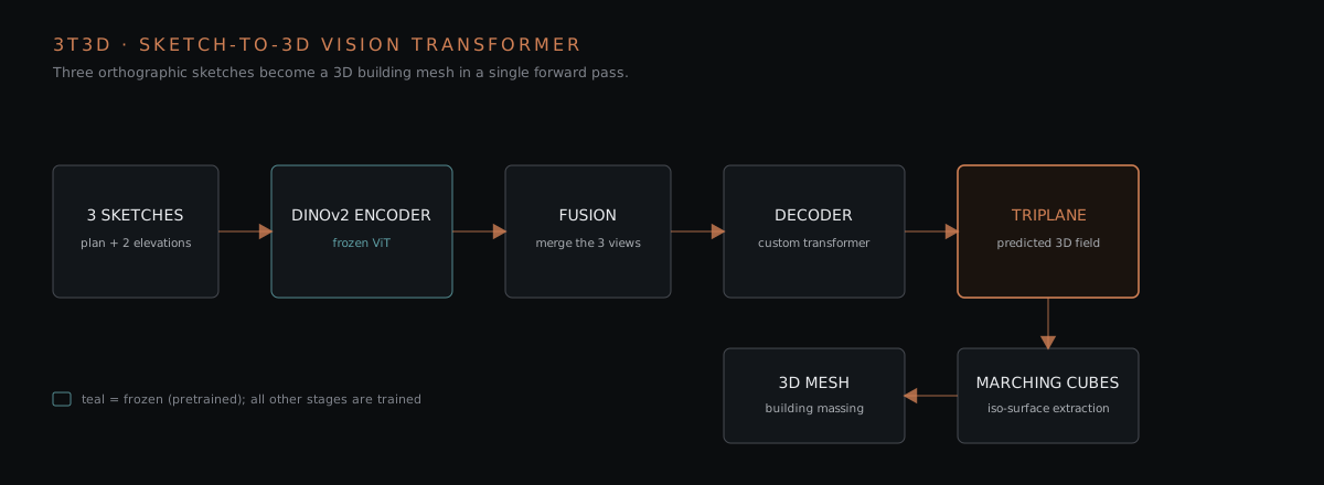
The model is a ViT encoder-decoder that maps three sketches to a triplane, following the stage breakdown from the writeup’s architecture table (B = batch, N = patches, D = feature dim):
| Stage | Operation | Detail | Output shape |
|---|---|---|---|
| Encoder | Input encoder | 3 image views → DINOv2 ViT | 3 × [B, N, D_enc] |
| Decoder | Input fusion | Linear-project each view to D_dec, then sum | [B, N, D_dec] |
| Decoder | Core decoder | Reshape, add 2D spatial pos-enc, transformer layers | [B, N, D_dec] |
| Upsampling | Upsampling neck | Reshape + ConvTranspose stages | [B, C_neck, H_out, W_out] |
| Output | Output layer | Conv 1×1 + Tanh → triplane channels | [B, C_out, H_out, W_out] |
1. Input processing
- 3 orthographic sketches — plan (top), front elevation, side (analogous to a floorplan + elevations)
- Rescaled from 256×256 → 512×512 for the encoder
- Concatenated along the channel dim into tensors of shape
[B, C, H, W]
2. Encoder — DINOv2 (frozen)
- Pretrained DINOv2 Vision Transformer, chosen for its positionally grounded multi-view patch embeddings and its implicit understanding of scene geometry
- Each view is split into patches; patches become tokens; patch embeddings are extracted per view
- The
clstoken is stripped (no classes in our training data)
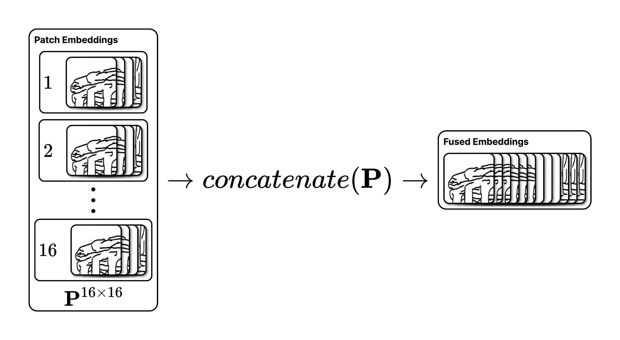
3. Fusion
- Each patch embedding produced by the ViT is assumed to correspond to the same location in 3D across the three views
- Fusion linear-projects each view’s embeddings to the decoder dimension and sums the co-located patches into a single fused feature vector, which is passed to the decoder
4. Decoder — custom transformer
- 6 decoder layers, 8 attention heads each, self-attention, pre-norm
d_model = 512, per-headd = 64, feed-forward512 → 2048 → 512with ReLU + dropout (from the decoder-layer diagram)- Sized as a deliberate trade-off between runtime, model size, and output quality — “where we had to do the most engineering”
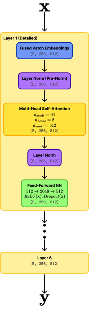
5. Upsampling → triplane → mesh
- The decoded features are progressively upsampled by the ConvTranspose neck (R¹⁶ → R¹²⁸) and projected with a Conv 1×1 + Tanh to the triplane representation
- A 3D surface mesh is extracted with Marching Cubes by sampling and combining the occupancy field derived from the triplane
Triplane representation (the 3D encoding)
Following Shue et al., each 3D object is decomposed into three orthogonal 2D feature planes F_xy, F_xz, F_yz. To query a point p = (x, y, z), the model samples each plane and sums, then decodes with a shared MLP:
n_p  = F_xy(x, y) + F_xz(x, z) + F_yz(y, z)
NF(p) = MLP(n_p)          # neural field value at p
We experimented with two ways to encode geometry into the triplanes:
- Binary occupancy — each plane stores a single channel (
C = 1); the value at(u, v)is 1 if the projected point is inside the object, 0 if outside. Trained with BCE loss. - Normal map + SDF — each plane stores 3D surface-normal vectors, combined with the object’s Signed Distance Field (shortest signed distance to the surface). A richer target meant to teach finer geometry; trained with L1 loss (continuous regression).
Dataset — built from scratch
Existing 3D architectural datasets were unusable for us — too much detail granularity, or not enough quality for form exploration. So we generated our own paired sketch-to-mesh corpus:
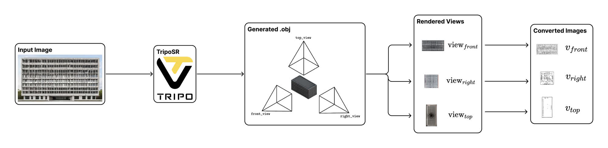
- Generate 1,800 building images with Stable Diffusion XL
- Convert each image to an
.objmesh with TripoSR; keep the best ~500 candidates - Render aligned front / top (plan) / side (elevation) views of each mesh
- Convert each rendered view into a sketch-like edge map via Informative Drawings
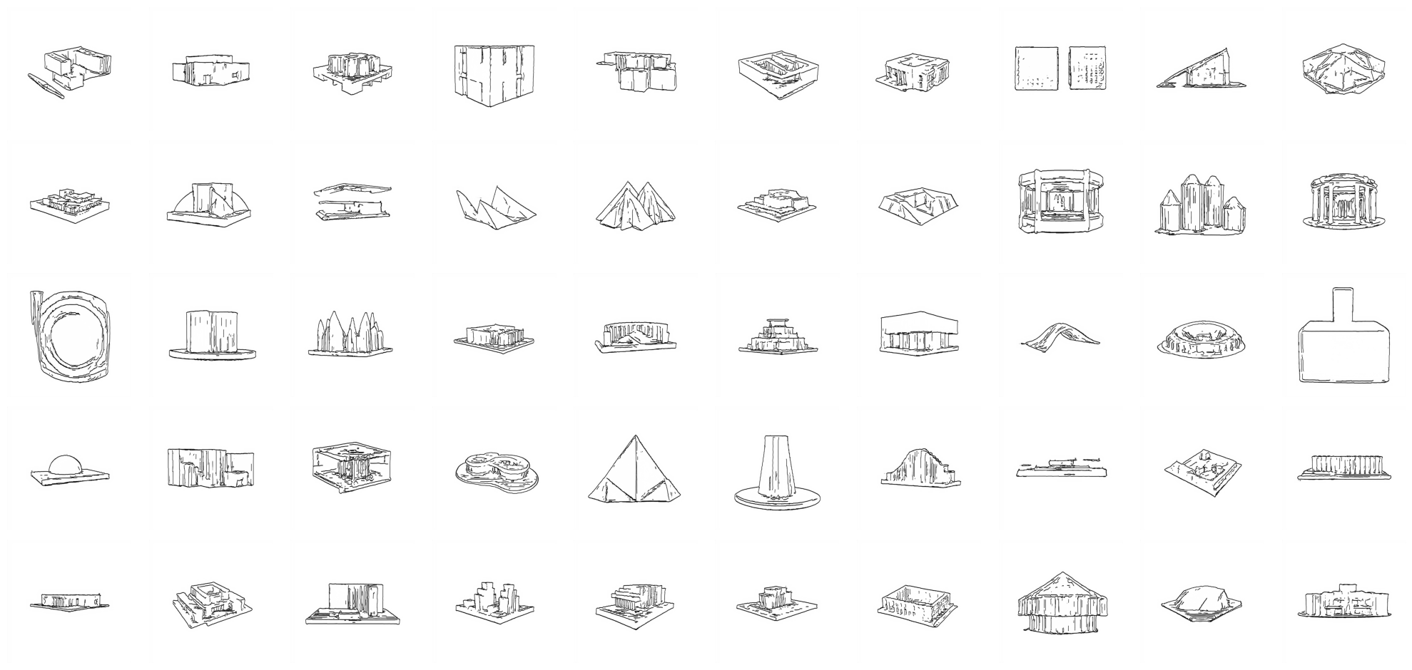
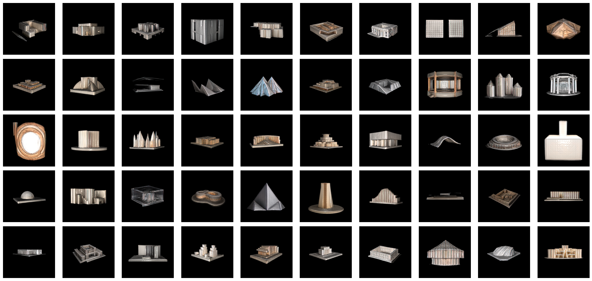
- Result: triplets of (front, right, top) edge-map sketches paired with a 3D mesh (
.obj), each converted to a ground-truth triplane target
Dataset samples:
| Sketches | 3D Models |
|---|---|
 |  |
Dataset structure (public, Google Drive):
Dataset/
├── sketch/
│   ├── front/     # Front view sketches (.png, .jpg)
│   ├── right/     # Right view sketches
│   └── top/       # Top view sketches
└── 3dmodel/ # 3D meshes (.obj files)Training
- Loss depends on the triplane encoding: BCE for binary occupancy (per-voxel occupied/empty probability), L1 for the normal-map + SDF triplanes (continuous regression). The Triplanar DDPM baseline used cross-entropy.
- Two-stage schedule:
- Freeze the DINOv2 encoder; train the decoder only until predictions are good
- Unfreeze the entire model; fine-tune with differentiated learning rates (low for the pretrained encoder, higher for the decoder)
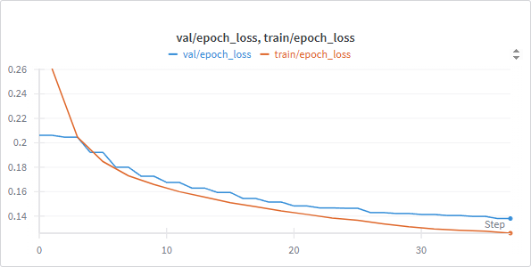
- Compute: 37 epochs on a single A100, ~480 s/epoch, ~5 hours total.
- Tracking: Weights & Biases.
Results
We report bidirectional Chamfer Distance (CD) between predicted and ground-truth meshes — a fairer comparison than pixel losses given the idiosyncratic output. The binary-occupancy model performed best; the normal-map + SDF variant produced plausible SDFs but smoothed normals, suggesting the richer target needs more architecture/optimization work.
| Metric (binary-occupancy model) | Value |
|---|---|
.obj models evaluated | 300 |
| Mean CD | 0.200 |
| Median CD | 0.192 |
| Min CD | 0.075 |
| Max CD | 0.429 |
Against reference models (lower CD is better) — 3T3D is competitive with the closest baseline but well short of dedicated single-image reconstructors:
| Model | CD |
|---|---|
| TripoSR | 0.111 |
| TGS | 0.122 |
| ZeroShape | 0.160 |
| OpenLRM | 0.180 |
| 3T3D (ours) | 0.200 |
| One-2-3-45 | 0.227 |
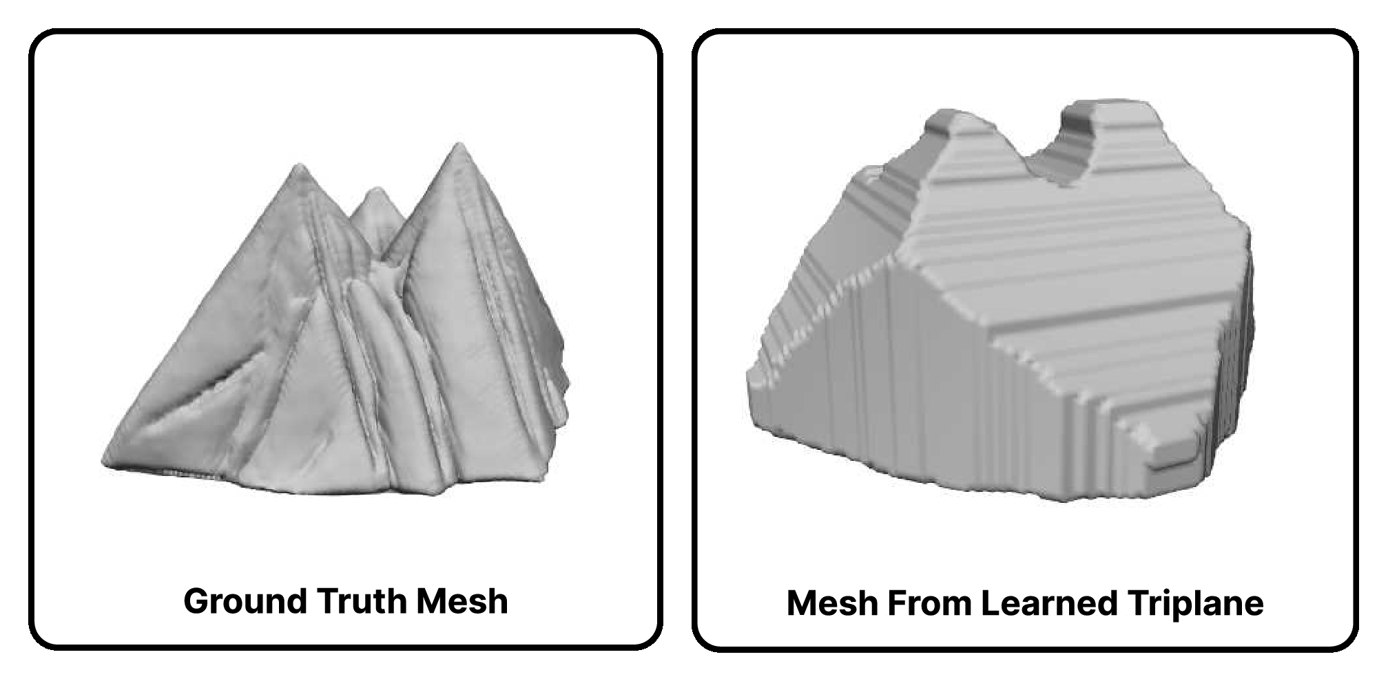
An analysis of CD vs ground-truth mesh complexity showed mean CD decreasing as vertex count grew — the model reconstructs more complex geometries with lower error within the tested range. The loss curves fall slowly but steadily; the team’s honest read is that hyperparameter optimization and longer training would close much of the gap. Example output vs ground truth:
Outcomes & honest assessment
- Feasibility demonstrated — 3T3D shows a ViT + triplane pipeline can do sketch-to-3D for architecture, a domain most 2D→3D work ignores in favor of object categories, with a mean CD of 0.200 that beats one baseline (One-2-3-45) while trailing dedicated single-image reconstructors.
- What didn’t work yet: the richer normal-map + SDF encoding was harder to learn than binary occupancy; the model trains slowly. The writeup is candid that architecture refinement, hyperparameter optimization, and longer training are the open work — this was a course project under a hard deadline, not a finished system.
- Reusable dataset pipeline: SDXL → TripoSR → rendered views → Informative Drawings edge maps → triplane targets is a repeatable recipe for building paired sketch/mesh corpora when none exist.
- Published dataset on Google Drive; final writeup PDF (
/assets/3t3d-vit-2d-to-3d/3t3d_writeup.pdf); final presentation on YouTube. - Flagship portfolio piece — my most substantial ML-systems work alongside [[2025-Fall—l43d-cad-mllm|L43D CAD-MLLM]]; the two share 3/4 team members and continue the same “designer-facing generative 3D” thread.
My contribution
Four-person team, flat structure (no group lead). I am first author on the writeup, and my work concentrated on the data, evaluation framing, and the paper:
- Dataset provisioning & management — built and shared the paired sketch/mesh corpus, provisioned the Google Drive folders the team trained from.
- Literature review — surveyed the sketch-to-3D and triplane landscape (CLIP, TripoSR, DINOv2, pix2pix3D, Neural Field Diffusion) to select the encoder backbone, 3D representation, and baselines.
- Experiment tracking and the technical writeup (the team’s “Overleaf master”).
The other three (Graham Felton, Chia Hui Yen, Karthick Raja) drove much of the model/decoder engineering and the training runs. Note: not all GitHub commits attribute to my chentianle1117 username — Colab sessions often committed under alternate identities.
Reference lineage
| Reference | Use |
|---|---|
| DINOv2 (arXiv:2304.07193) | Encoder backbone (frozen ViT) |
| Stable Diffusion XL (arXiv:2307.01952) | Building-image generation for the dataset |
| TripoSR (arXiv:2311.04400) | Image→mesh step of the dataset pipeline |
| Informative Drawings | Rendered views → edge-map sketches |
| Triplane diffusion (arXiv:2302.08509) | Triplane 3D representation (Shue et al.) |
| pix2pix3D | Conditional-synthesis baseline (Deng et al.) |
| Marching Cubes | Mesh extraction from the occupancy field |
| CLIP | Considered for early pipeline |
| Hunyuan3D-2 | Considered |
| TriplaneGaussian | Considered |
Artifacts in vault
Under Portfolio//assets/3t3d-vit-2d-to-3d/:
| File | Size | Purpose |
|---|---|---|
3t3d_writeup.pdf | 1.8 MB | Final project writeup (pulled from repo /img/) |
project_notebook.ipynb | 5.1 MB | Final project notebook (from team WhatsApp) |
dev_triplane.ipynb | 1.7 MB | Triplane representation development notebook |
dev_with_validation.ipynb | 2.9 MB | Training + validation notebook |
arch_diagram.jpg, fusion_diagram.jpg, decoder_diagram.jpg | — | Architecture figures |
dataset_creation1.jpg, data_sketch.png, data_3d.png | — | Dataset pipeline + samples |
val_train_loss.png | — | Wandb training curves |
comparison.jpg | — | Model output vs ground truth |
Links
- GitHub: chentianle1117/3T3D — David’s personal fork (primary link for portfolio; preserves the project under his name)
- GitHub: 1gfelton/3T3D — upstream canonical public repo on Graham’s account (READMEd, polished for public use, writeup PDF)
- GitHub: 11-685-Team-52/3Ts-Model-for-Architectural-design-process — team’s shared working repo with 3 notebooks:
3_2d_to_3d_w_validation+dataaug_2504.ipynb(29 MB, late-iteration data-augmentation version),ImageGEN-Chia.ipynb(1.1 MB — Chia’s dataset pipeline),triplane_encoder_decoder.ipynb(74 KB) - Final video presentation (YouTube)
- Public dataset (Google Drive)
- Final writeup PDF (in vault):
/assets/3t3d-vit-2d-to-3d/3t3d_writeup.pdf - Overleaf report source: https://www.overleaf.com/project/680ad1d4af18bc319d37a756
Related cards
- [[2025-Fall—l43d-cad-mllm]] — same core trio (David + Chia + Karthick) + Yizhuo Di, extending the generative-3D arc into multimodal CAD